Tuesday, March 31, 2015

The spark generating flash
This is the point where I start mentioning disclaimers. Don’t do anything that I have done here, you could seriously injure yourself (if you actually survive). Capacitors store a lot of energy at high voltages that can kill you! These illustrations are for the interest of those who are fully capable of working with high/dangerous voltages and should not be copied by anyone.
When a flash is turned on and the capacitor is charged up the voltage from the capacitor is always making contact with the flash tube and the wires are always live, even after the flash has been turned off the capacitor holds a charge for a dangerously long time. There is a trigger wire just off-centre of the flash tube that ionizes the gas in the tube to fire the flash at different powers, depending on the time of the trigger voltage.
I will repeat this for emphasis: The capacitor is permanently connected to the flash tube and the wires at either end are always live even when the flash is not firing and for a a long time after it is turned off! 
Now let’s have a look at a flash that has been modified to generate a spark when it fires. 

The basic principle involved here is that if an ignition coil is wired in series with the flash capacitor it will share some of the energy of the capacitor discharging through the flash tube. I’m not sure how much of that energy; all I know is that with most of the reasonably powerful flashes I get a spark equivalent to about 30 000volts. With one design I added a second capacitor in parallel with the main flash capacitor, which is similar to jump-starting a car with another battery.  This gave me a spark that jumped a gap that was probably equivalent to about 50 000volts. Who knows, it’s impossible to actually measure that voltage so it is merely assumed based on a table of distances and gasses etc. In the image below it is jumping a small gap, it jumps a 5cm (2 inch) gap when required.

And when you consider the fact that the flash is firing pretty brightly as well it shows how much more power could be available for a spark if we didn’t have to share it with the flash tube. 
Now for the wiring diagram, to show you what you shouldn’t attempt. If a flash head is opened, the old hammerhead style flashes are easier to get apart; you will find a tube with a wire at either end. These two wires are connected to the capacitor, which usually has around 300volts available - which is enough to blow off your fingertips while frying your heart. Starting to get the picture? Now if one of those wires is cut (either one) and two extension wires are connected up to be joined to either end of an ignition coil, the flash will still fire but some of its energy will be used up, in the coil to generate a spark, while the rest is released as light energy. The HT (high-tension) lead of the coil will need an earth wire and the side that it needs to be connected to will depend on which side of the flash tube you cut into and which way around the coil is connected. Play around with both options and see which gives the best spark.

There are obviously technical ways of working out which way around to connect the wires on the coil and which side of the coil to connect the earth lead to but generally it is much simpler to just try different variations and see which works best. Of course you could spend hours learning about the actual theory of it all and get it right by logically working out which way around it should be connected but there is always the possibility that the coil you decide to use isn’t wired up the way the text books suggest it should be. To me it’s just not worth the bother, decide what you want to do, connect things up, and see what works best – it’s worked pretty well for me so far! 
So what is the purpose of this exercise then? Well for one thing you now have a tool that generates a 30 000 volt spark (approximate of course) each time you take a photo. 
You could put the HT lead next to some water and put the earth lead inside the water. 


If you are using a normal camera with a focal plane shutter you will be limited to the flash sync speed of your camera, usually around 1/200th of a second. I’m not going to go too much into the focal plane shutter, I did that in my first book “Photography Masterclass”, but I will make mention of a rather ‘special’ camera that is good for this type of thing.
In fact there are several models to choose from that have a CCD sensor. The Nikon D70/S, D40, D50 are the main ones I can think of. They are special in that they can sync flash at 1/500th of a second and faster if you trick them. They do not use a focal plane shutter that simply varies the size of the slit for speeds above 1/250th. Instead the whole sensor switches on and off to capture the exposure. This means that when the flash fires the entire sensor is exposed to the light every time, even at maximum shutter speed. They have disadvantages like sensor bloom (bright patches) when shooting into bright lights so they don’t make them like this any more . I love these cameras and do a lot of my work with the D40. If you use a hotshoe adapter and pc cord the camera doesn’t know there is a flash connected so it doesn’t limit your shutter speed to 1/500th when you’re doing ‘different’ photography. 
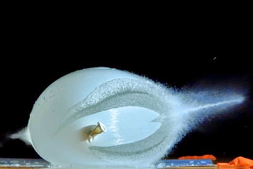
As an example of what I am talking about I’ll show a range of images of a spark taken at various speeds with the D40 and the spark-generating-flash system. This is what I call “superspeed” photography, the act of photographing an event that you have triggered by pressing the shutter release. Any camera can do this speed. 

Only a camera with 1/500th sync speed can do this. Try it with a camera with a focal plane shutter and you will perhaps see half a spark as the slit of the shutter blocks half the screen. You could frame the image with the spark in the top half and capture it though, just the bottom half will be blacked out. 

Now we go to higher speeds. 


And the fastest shutter speed the D40 can do. 

The way I see it this set-up can be used as a scientific tool. Photographing an event at a set speed that you know is generated when you press the shutter. I think it has a lot of potential. 
Once I got this working I thought I had it made. Now I could start photographing gas explosions! What a disappointment though, it’s not easy making a gas explosion no matter how much the fuel stations get our hopes up. The air-fuel ration has to be pretty good or nothing happens. I had a bag full of petrol with a 30 000 volt spark jumping from above the liquid’s surface right down to the earth wire under the surface and still nothing happened. The mixture was too rich, not enough oxygen. Eventually I got a lame burst of flames from a reasonable mixture of air and gas but nothing to write home about. 

I’ll just emphasize what people say about my photography at this point. The pictures aren’t very artistic but what’s the point of setting up fancy backgrounds before you even know if something will work? I know they are right, I look through my images and they all look pretty ‘mechanical’ but wait till I get the technique right before hurling any more accusations, once I have perfected my methods I start getting artistic, it’s just that I’m still working towards perfecting them but sharing what I have learned so far in the meantime. 
My next idea was to buy some gunpowder, I had never worked with the stuff before and in hindsight perhaps the container shouldn’t have been so close to my experiment area. Why do people keep giving me fire extinguishers??? 


The experiment was a failure; a spark does not ignite gunpowder. Electricity simply looks for the easiest path to the earth connection, which involves pushing the granules of gunpowder out of the way to get there. 

Occasionally I saw a glimmer of hope but knew this wasn’t reliable enough to start getting artistic. 

The next step was to use something that would slowly produce some gas in an existing oxygen rich environment. It’s a good thing my microwave volunteered for the job by not working a few days later when I wanted to use it. I had no hesitation in buying a replacement rather than trying to have it repaired, I had plans for it. 

That was the best image I got from my D90 at 5fps but if you look up “fireball two” on YouTube you can watch a video taken at 400fps with the Nikon J1, another useful high-speed tool. This exercise involved throwing a teaspoon of Calcium Carbide in a can of water, which results in the release of Acetylene gas. The spark-generating-flash ignited the mixture as I took the first photo with the D90. I’m not after a loud noisy destructive explosion, just a nice fireball.  I made some low quality screen captures of the video, which shows a few stages of the fireball.
First the flash fires and generates a spark igniting the mixture.

The flame front starts to spread.

Eventually the fireball reaches out of the microwave oven.


The spark-generating-flash system provided me with some interesting images and may prove useful with exact air-gas mixtures but I needed something more reliable if I wanted to photograph a decent explosion. This led me to do some research and learn about the Silicon Controlled Rectifier (SCR).

Superspeed Photography
Something that I consider “my invention” because I haven’t heard of it being done before is “superspeed” photography. It is the act of photographing an event that would not have taken place if you had not taken the photograph. It can be faster than high-speed photography in that your camera’s fastest shutter speed can be used rather than using a 1 or 2 second exposure while relying on the flash to freeze the motion. It is also more reliable than using a fast frame rate on your camera because the event happens because you pressed the shutter, not because you were trying to photograph the event. 
How does it work? Basically you are using the flash triggering circuit of your camera to make the event happen, so it happens as quickly as the action of your flash firing in many cases, and as reliably as the flash triggering circuit in your camera. 
The flash triggering circuit in your camera is basically a switch that joins the centre and side pins of your flash together as you take a picture. In most reasonable cameras this can handle up to 250 volts while some can only handle as little as 6 volts so just check the specifications of your camera before trying any of this. A work-around if you’re not sure is to use an optic trigger and fire your camera’s flash to trigger that so you don’t have to worry about damage to your camera’s electronics. 
Most cameras have a focal plane shutter which means that any speed faster than the flash sync speed (usually 1/200th or 1/250th of a second) involves the shutter becoming a slit that slides across the frame to limit the amount of light impacting on the sensor (‘sync’ is basically the synchronization speed of the camera and flash). So at 1/500th of a second instead of the shutter opening and closing in one movement the first ‘curtain’ starts opening and as it gets halfway the second ‘curtain’ starts closing resulting in a slit half the original size sliding across the frame and therefore half the light as at 1/250th affecting the exposure. 
Here are a few pictures to make this clearer. An old Canon camera with the back pulled off has a flash sync speed of 1/90th of a second. When it fires you can see the entire frame. 


But when we add an external flash and fire that at 1/1000th of a second the focal plane shutter has now become a slit to give less than 1/10th of the light of 1/90th meaning that when the first curtain reaches the bottom, and fires the flash, all that is affected by the flash is a small slit at the bottom of the frame. The flash fires as the ‘first curtain’ reaches the end of its travel. Most people who experience this problem with using a flash at high speeds report a dark part at the bottom of the frame meaning that their camera’s shutter curtains move from the bottom to the top of the frame. 

The size of this slit will vary depending on the chosen shutter speed, how much faster it is than the camera’s maximum flash sync speed, and the ratio of those speeds. In other words if a camera can sync flash at 1/250th of a second then at 1/500th the slit will be half the size of the frame, at 1/2500th it will be 1/10th of the frame and so on. 
This will be a major factor in any experiments you conduct, how much of the frame will be affected at high speeds, so try to stay within your limits in the beginning. If you have a camera like the D40/50/70 you can use any speed, which will be explained later. 
So how does superspeed photography work then? The simplest approach is to modify a flash, which is very dangerous if you don’t know what you are doing, and even if you do! If you open the end of the flash you will find a tube with a wire at each end, and one near the middle. Do not touch these wires with your bare fingers! Always take the batteries out of a flash when working with it. I usually turn it on, fire it at full power and immediately turn it off again to try to dump the energy from the capacitor. Even then it is could still have a charge in it so you still have to be very careful with it. It’s handy to have a 240 volt light bulb with two wires coming off it to connect to those wires and discharge the capacitor. The scary method is to touch both wires with a solid piece of wire and watch the spark blow a piece of the wire off as it discharges. 
Even after taking all these precautions it is still best not to touch any bare wires. I simply snip one wire (any one) at the end of the tube and join two longer wires to them to connect to whatever I am putting in series with it. 
Here is a diagram to illustrate this concept. 

My first attempt at superspeed photography was trying to burst a balloon full of water in daylight. The early exposures didn’t work because of the time it takes for a solenoid to pull in. I used a control solenoid from a diesel fuel pump and put a needle at the end of the plunger. As it pulled in it burst the balloon full of water. Due to the lack of control in the situation, a shaky stand with a balloon full of water and strong winds, I eventually had to drop to 1/30th of a second to give the needle time to reach the balloon. This resulted in something that looked like a double exposure as the original shape of the balloon was captured plus the burst a fraction of a second later. I would call this the first successful image of superspeed photography. 

Summary: Superspeed photography involves capturing an event you have created by the act of pressing the shutter and with the right technique can be used at any shutter speed. From here on we will be using this technique for creating 

moments of destruction.

Sunday, March 29, 2015

The sound activated flash trigger.

The sound activated flash trigger

One of the most useful tools for high-speed photography is the sound activated switch. The one I use is sold as a “voice activated switching circuit” that has to be assembled first following their ‘simple’ instructions, Hmmmmm! Well I’m pretty sure that you can buy a ready made trigger kit just about anywhere in the world but most things cost a little more in New Zealand so I bought a kit and took the chance that it didn’t exactly need a human voice to trigger it. Well it worked after I put it together which is always a bonus, and it also triggered with any sound that was loud enough, so obviously it wasn’t ‘voice activated’ but rather ‘sound activated’. 
The biggest ‘secret’ of modifying electronic circuits is that the small parts do the thinking while the bigger parts do the work. Have a look at the circuit of my sound activated switch for example. Pay particular attention to the white box thingy on the right that I have marked as ‘relay’.

We have a lot of little components that do all the thinking and calculating but they are the ‘brains’, not very strong but clever just the same. The relay is the muscle, not very clever but strong, because it is made bigger particularly for that purpose. So how does all the circuitry work to trigger the flash? Who cares? It just does! If you’re only interested in using it to help your photography then you don’t need to know and quite honestly I’d have to read up on it again [I forget easily] to remind myself how it works which, in any case, won’t make any difference to the final images now will it! All you have to remember is that if you want to modify something for triggering a flash you just have to find the final output of any circuit and connect the wires to that. 
So we have the white box thingy and three contacts called “nc”, “com”, and “no”. They stand for “normally closed”, “common” and “normally open”. A photograph of a similar relay pulled apart will help to understand this easier. 
In its rest position the normally closed contacts are touching the common contact. The blue thing on the left is the electromagnet winding which works the same way as what many of us learned at school, a winding of wire around a piece of metal makes a magnet when electricity is applied.

The components that form the brains of the circuit supply electricity to the winding contacts under the right conditions and the contacts, which are not in any way connected to the circuit, get pushed by a lever so that “common” touches “normally open” and so becomes a “closed” circuit. 

I will repeat this for emphasis: The three contacts “nc”,”com” and “no” are not in any way connected to the rest of the circuit. This means that even if the board itself uses a 12volt supply, you can switch a 300volt feed with those contacts without harming your 12volt circuit. You don’t have to worry how many volts an old flash triggers at to use it with a relay. If, however, you need to know how many volts an old flash triggers at do a search “Botzilla strobe voltages” for a handy list of measured flash trigger voltages - very useful site.
We want to use the “normally open” and “common” terminals. Cut one end off a pc cable and join the two wires to those connections and when the circuit switches the relay the flash will fire, if it has the pc plug connected of course. If you want it to switch really fast, which you probably will, you can take out the mechanical relay and replace it with a solid-state relay. 
What you will have to remember with a solid-state relay is that besides the fact that it has no moving parts and switches almost instantly, it is ‘polarity sensitive’. This means that what would be the “winding contacts” are electronic components that may require that they are switched with positive and negative on the correct terminals, unlike a mechanical relay which doesn’t care. Just be sure that you get a dc and not an ac relay if you do decide to upgrade to solid-state. 
The switched side of a solid-state relay is often also polarity sensitive, as are the components inside your flash trigger circuit. This means that you will have to experiment with which way around you connect the two wires from the pc cable because it may work one way around but not the other.
The next step, if you want it to look fancy, is to put that circuit board in a plastic box and have the wires outside ready to be connected to your flash. 

A good mechanical relay can switch in 5ms but that’s already 1/200th of a second and quite often that will be much too late to capture a smashing event. So let me share my modification with you. Now just keep in mind when you see my picture that “The shoemakers children go to school barefoot”. In other words I’m an auto electrician and there’s no way I am going to spend my precious time making a perfect looking unit when I’m not getting paid to do it! Just be grateful that I finally actually put it in a plastic box because before it was just a mess of loose wires before. My unit is modified for long distance work with regard to keeping away from water and being able to adjust working distances for timing, in other words – longer cords. 

And here’s a close up of the solid-state relay and its wiring. At the top right is a picture of the top of the solid-state relay I used. I left the original relay in for a reason, it could be removed but sometimes it is handy hearing the ‘click’ so you know when something switched even when the flash isn’t connected. But be wary of having the mic too close to that click because it could keep switching itself on from that noise. If you hold the board up to the light you can see the shape of the original relay and the two switching pins on the opposite side of the switched “no,com,nc” pins. These are the pins you will need to connect the switched ‘input’ terminals of the solid-state relay to. And of course the output “load” terminals of the solid-state relay will trigger the flash via the pc cord. Just twist the wires onto the pins when you first connect it up because you may have to experiment with different configurations due to the fact that electronics often only switches electricity in one direction. If it doesn’t work one way try swapping the 1 & 2 terminal connections over, then the 3 & 4 connections until it triggers the flash. It’s too complicated trying to learn which way around they should go from the beginning for the once you will probably ever do it, so just test it first with the normal relay to make sure everything works and then do the Solid-state mod if you want the extra switching speed. 

Now we’re ready for action! The red and blue terminals will plug onto a 12volt security battery, the microphone wires have been extended to keep them away from the box which was transmitting vibrations and interfering with my ‘progress’ by triggering the flash again from the sound of the relay switching, and the long pc cable makes it easier to keep the box away from breaking glass and splashing water. 
My first attempts involved shooting balloons with an air rifle. The first step is to get the right working distance because it all happens so quickly that distance, which equates to timing, is crucial. Think about the variables we have: 1) the speed of sound, 2) the distance that sound has to travel, 3) the speed of the pellet, and 4) the distance the pellet has to travel to do its damage. The switching time of a mechanical relay would also have to be taken into consideration if you don’t upgrade to a solid-state-relay.
Find yourself a comfortable distance to work at without you or your camera gear getting splashed. Keep that distance constant. Here are some examples to illustrate the importance of this part of the equation. My first ‘shot’ involved the microphone right under the air rifle which was touching the balloon. 

The sound of the air rifle going off triggered the flash so soon that I had a picture of a balloon with a pellet somewhere in the middle perhaps. I moved the microphone a little further away to give the balloon time to burst but it was all over so quickly it was pointless. 

The solution was to stand further away to increase the variables available for adjustment. I stood 2 meters away and shot above the balloon so I could see the pellet’s position when the flash fired, and adjusted the distance the mic was away to get it where I wanted it in the picture. Take a photo and the pellet is in front of the balloon, move the mic further away and take another photo so the sound has further to travel to trigger the flash. Keep doing this until the pellet is where you think it should be in the photo. Eventually I had a balloon with a pellet just behind it in the picture. 


Shooting the balloon full of water was a different story though because now we had the pellet hitting something that slowed it down a bit and all I got was a small split. That was another variable to consider. 

At this stage I was still experimenting so the background isn’t too nice. Good excuse eh! Actually I just hadn’t put enough thought into it yet
The above image was taken when the mic was about 2 meters away from the air rifle. When I moved it to about 4 meters away and took the next picture I stood and stared at the screen for a while, thinking there was something wrong with my camera’s display because I had never seen anything like it. As the balloon splits the rubber pulls the water up in a spray that looks a bit like a starfish.   

Once we have our flash power, and distances to the subject and mic right, it becomes a mechanical action. Just remember to fill the balloons up to the same tension each time or another variable is created because they will split at a different speed if this isn’t done. Fill a balloon with water, place it on the ‘spot’ you have marked with a pen, camera on 2 seconds, F9 iso200, press shutter, pull the trigger and feel the thrill of looking to see what you have captured. At 1/11000th of a second flash time that’s 11000 slices of one second that you might have captured, it’s exciting to look and see which one it is! 
There was a pattern with the balloons I was using but perhaps it depends on how they are manufactured. Each split I got seemed to be 4, 6, or 8 way tears. Here are a few of the more well defined splits to show this. In hindsight I should have had another flash on the other side of each balloon.  

And here is a 4-way split. 

Once you’ve had enough of frontal shots you can move to the side and perhaps use a remote to trigger the camera. BUT! You will have to adjust your distances all over again because as soon as you move, the amount of time the sound has to travel to trigger the flash changes. Shooting from an angle or the side reveals a different perspective on bursting water balloons altogether! 

And one shot directly from the side. 

If you have the time to play with you can also put food coloring in the balloon, though this can be quite tedious, and messy. 
You may just be able to see the pellet coming out the back of the balloon, another reminder that having a second flash on the other side would have been a good idea. 

Then there is the option of hanging the balloon by a piece of string for even better definition of the frontal splits. [this one made it to National Geographic :) ]

Here’s a good argument for having a second flash directly opposite the main flash in the front. To add another flash simply set it up with an optic trigger and the same power setting as the first flash, and it will fire at exactly the same time! In this image I half filled the balloon and shot the top away. It is a pretty unique shot in that I got a vertical split. 

Once again we have the option of seeing the same photos shot from the side. If you have two cameras it would definitely pay to have them both set up to fire with a remote so you can get multiple angles of the same event. 

And if you aim higher ……

When you’ve had enough of tying the balloons up you can put them back on a flat surface and half fill them and shoot the top away. By this time I had learned to shoot with the camera low down so that I have as little of the table in the photo as possible. 

There’s always a different image no matter what you do. 

There are also many different options to explore with a half-filled balloon. I eventually resorted to shooting down on them. Of course I had a few wasted shots before I adjusted the mic distance to the correct position once again. This is the ‘yellow ship’ picture. 

So what do you do to protect your flash from all this water flying around? A 2 liter milk container is the solution. It isn’t pretty but it won’t be in the pictures, so who cares? 

And of course remember to adjust your mic distance after each position change or you could end up with a photo of a pellet touching the balloon. 

Let’s add another twist to the pictures. A mirror doubles our chances of seeing something interesting. Look at the back of that pellet in the top image. 

Occasionally something strange happens. In this image I only got a hole in the front with the split at the back. 

In the above image and the next one you can see the trail of the pellet leaving the balloon at the back. 


Shooting two water balloons at once gets messy; I never had much success with that approach. 


Of course you can do more than bursting water balloons with the sound activated flash trigger. On the circuit board in the picture I posted there are two adjustments. One is for sensitivity and the other determines how long the switch stays on for which means that you can make sure you don’t get a double switch within a certain time. If you place the mic so that it is near a piece of wood it will fire the flash when you drop something on the wood. A glass of water makes for some interesting images as well. 

Always something different …….

If you really want some interesting images collect old light bulbs. You will need a lot of space, perhaps a plastic tarpaulin on the ground to catch the broken bits, safety glasses and trousers that cover the top of your boots so glass can’t get to your feet. Smashing glass moves very quickly so you will need faster speeds. The lowest power setting on an SB800 is 1/128th, which fires at 1/41600th of a second. This certainly freezes the motion. Keep in mind though that motion is never truly ‘frozen’ because there is always some movement at any speed, it just gets less as you use higher speeds. It finally looks well and truly ‘frozen’ when the movement in the image is less than one pixel on your sensor so it can’t be shown. 
Here are a few samples of light bulbs breaking. If you hit the bulb normally it won’t look like this!

I learned that hitting the bulb straight down made for photos with a hammer almost touching the board. The trick is to almost ‘drop’ the hammer, which causes the bulb to smash and bounce upwards in one movement. This makes for a gap between the bulb and the board - just keep that in mind if you try it. The hammer has been edited out of this shot. 

As mentioned previously you never know what you will get. 

As can be seen from the last batch of images, by this time I had learned to get low down to the same level as the subject so that there is as little of the table as possible in the image. 

Once again this image shows that dropping the hammer rather than hitting with it means that you don’t get an image with the hammer touching the board. Rather, you get some space between them.

If you really want to test your flash speed to its limits try shooting the bulb with an air rifle. That’s when you realize that 1/41600th is not the solution to every speed. 

It can look quite impressive if you catch it right. 

I eventually got a dozen eggs and started cutting them with a sword, very unimpressive. Finally someone on the forums suggested I try shooting some eggs. I replied that it probably wouldn’t look like much and set out to prove myself right. 
The first image didn’t look impressive at all but I was surprised to feel something cold hit my face, and saw some yellow stuff on my camera. The yoke was on me, it had obviously moved further than the early stage of the explosion that I had captured. 

The solution, when an event is captured too early, is to move the mic further away and try again. It looked a lot better and there is still much room for improvement regarding the background, but I feel kinda bad destroying food like that so I left it at that, the final eggsplosion. 

All this time I had been using the sound of the air rifle to capture the events resulting from it’s firing. I decided to capture a few of the air rifle itself. The early photos didn’t look like much until I sprayed some anti-rust spray down the barrel before each shot. Look at the puff where the barrel supposedly seals halfway, showing the leaking seal. 

Moving the mic a little further away meant that the pellet could leave the ‘puff’ behind and be more easily visible.